Calibrating a Wireless LAN Survey Plan
One of the most important steps in completing a WiFi network survey using a professional survey tool is to ensure that you have a correctly calibrated the floor plans used to conduct the survey. Without this step, your survey may be inaccurate or, at worst, worthless. In this article we look at why this is important, together with the right (and wrong) way to do it.
Background
When performing any type of WiFi network survey using a tool such as Ekahau’s Site Survey or Fluke’s AirMagnet, one of the first tasks performed is the creation of a survey project. During the creation of the survey project, a number of configuration tasks must be performed. One of mandatory tasks is to import an electronic copy of the floor plan of the area to be surveyed.
The floor plan is generally an image file (jpg, png, bmp etc.format) that has been created from an architect’s blueprint of each floor of a building. Professional survey tools also often allow the import of AutoCad (DWG) files directly, though I personally have had mixed results with this method.
The purpose of importing a floor-plan is to allow radio frequency measurements to be plotted by a surveyor as he/she moves around a survey area. The usual methodology involves walking around a facility, clicking on the imported floor-plan to indicate the surveyor's current position. At each point, radio frequency measurements are taken, recording signal and noise levels for various frequencies.
Predictions and Assumptions
When performing a survey, each time a point is clicked on the floor plan, the survey software will take a measurement at that discrete point, However, this measurement only applies to the precise spot that the surveyor is standing on at the time the measurement is taken. To take readings at every point on the floor plan would take a colossal amount of time, and would involve a surveyor shifting a few inches each time he/she took a measurement, in order to obtain measurements across the whole coverage area.
To avoid this issue and make the whole surveying process more practical, the survey software makes a prediction about the signal coverage around the point where each measurement has been taken. It will make an educated “guess” about how the radio frequency signal will look in the immediate vicinity of the point where the measurement is taken. It uses some clever maths to predict how the signal will look in a guess “zone” around the measurement point, based on how an RF signal reduces in a predictable manner over a known distance (Free Space Loss). The "guess" distance is generally around a 2 - 5 metre radius around the measurement point (which is user-configurable).
The example below shows a very simple walk-path, with the RF signal level shown with a 2 metre radius around each sample point:
The example below shows a very simple walk-path, with the RF signal level shown with a 2 metre radius around each sample point:
 |
| Fig. 1 - Survey path in Ekahau |
Predictive (Desktop) Surveys
So far, we've only discussed “physical” surveys that involve a surveyor being present on site, assessing the RF environment by taking regular measurements as they move through a survey area. Another survey technique that may be used is a predictive (also often known as a “desktop” or “off-plan”) survey.
This survey again requires a plan to be imported in to the survey software, but also requires information about obstructions in the area to be provided. Obstructions are mapped on to the floor plan, with each obstruction classified by the material that it is made from (e.g. brick, concrete, wood door). The position and characteristics (i.e. the RF loss) of the obstructions are used to calculate/predict the effect on radio frequency signals for access points placed around the floor area. A key input to the calculations performed is the rate at which an RF signal reduces (in a predictable manner) over a known distance (Free Space Loss).
To create the survey report, “Virtual” APs are placed on to the imported floor plan and the antenna type and transmit power of each AP are configured. The survey software then creates a predictive model of the RF environment and the coverage that the APs will likely provide when real APs are deployed in those same positions.
Physical Dimensions
In both of the survey scenarios we have summarized, the physical size of the survey area is a key component of the recording or calculation of signal measurements, and hence the final report that will be created.
In the case of a physical survey, the coverage provided by each survey point is predicted by the survey software around the immediate area that each measurement is taken. Correct scaling of the survey plan is critical to ensure that the expected signal propagation data is correct across the survey area.
Predictive surveys rely on no measured data at all, so are reliant purely on calculations to show expected RF performance. If the scale of the floor plan used for the survey does not accurately reflect the dimensions of the area surveyed, then the mathematics used to create the predicted coverage data will simply be wrong (and hence, useless).
Floor Plan Scaling
We’ve hopefully presented the case for why floor plans must be accurately scaled to ensure that accurate survey data will be created by a WiFI survey tool. Now we’ll take a look at how we actually achieve this. In theory, it’s a simple operation, which is pretty much the same in all tools: simply highlight a physical object on the floor plan that is a known length (e.g. a building wall) and enter its actual physical measurement. Sounds simple...right?
Once a floor plan has been accurately scaled, we can be confident that the data presented in our survey report is going to be as accurate as possible and will actually reflect the real world. Skipping or short-cutting this step can lead to a whole heap of pain when your final network deployment simply does not work, as your original survey report did not reflect the actual physical area to be covered.
Don’t Use a Door
If there is one piece of advice that you take from this article it’s this: DO NOT use a door on a floor plan to scale your survey project. As tempting as it is, for ease and speed, do not rely on the "known" measurement of what you perceive to be a “standard” door. Unfortunately, I see this approach used by far too many wireless survey engineers, which is simple asking for trouble.
Speaking with various engineers, I have heard that a “standard” door is : 90cm, 1 metre, 3 feet, 3 feet 6 inches, 4 feet….<add your own estimate here>. In short, you cannot assume the “standard” size of any door - particularly if you have never even visited the site in the case of a predictive survey.
Even if you are on site and can measure a door, looking at the size of the door on the plans of most typical floor plans, can you really accurately highlight such a small area on such a large plan? Even when zooming in to the door on a plan, you tend to end up with an indistinct, pixelated feature (see below).
Even if you are on site and can measure a door, looking at the size of the door on the plans of most typical floor plans, can you really accurately highlight such a small area on such a large plan? Even when zooming in to the door on a plan, you tend to end up with an indistinct, pixelated feature (see below).
| Fig. 2 - Could you really scale these doors accurately !? |
The door example highlighted above introduces a valuable concept. Smaller features tend to be much more difficult to highlight and measure on a floor plan and are likely to introduce greater margins of error.
For example, we might take a doorway that is perhaps 1 metre (100cm) wide and try to use this to scale our plan. Due to inaccuracies of plotting such a small feature or due to plan pixelation, we may be a few centimetres adrift in our attempted measurement. In terms of a percentage difference between our measurement and the real world, this may easily become a significant proportion. For instance, if our door measurement is incorrect by 5cm, this translates to a 5% error. 10cm would translate to a 10% error. If we then scale this up to the effect on (for instance) a warehouse, you can start to imagine how a 10% error across an area of many thousands of square metres is not a desirable situation. You could easily end up under or over-provisioning, depending on which way your margin of error fell.
The best practice approach is to use as large a feature as you can accurately measure. A small error on a larger measurement is generally going to introduce a much smaller margin of error. For instance, if measuring a 100 foot wall, if your measurement is one or two feet short, you are only looking at a 1 or 2% error: far less damaging than when we tried to use the smaller dimensions of a door.
Measuring Options
Although we’ve established that using the longest measurement you can accurately measure is going to yield best results, you may be wondering exactly how to measure the dimensions of your chosen feature. We have quite a number of choices, but all will yield accurate results if used carefully.
Tape Measure
The most obvious choice for measuring the size of your chosen feature is probably a traditional tape measure. It’s worth choosing one that is longer than the general purpose DIY-type measures which are generally only around 25 feet in length. 100 or even 200 foot tape reels are available which are very inexpensive and will allow measurements of much larger features.
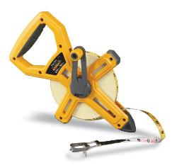 |
| Fig. 3 - Tape measure |
For even larger distances (generally up to around 1,000 feet), a measuring wheel also provides a good option.
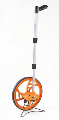 |
| Fig. 4 - Measuring wheel |
Laser Measure
Although tape measures and reels provide a very cost effective method of measuring distances, they can be a little cumbersome to use. It may often not be convenient to measure between 2 points due to a variety of obstructions or even staff and machinery moving in the area where measurements are being taken. Also, extended distances may require two people to take a measurement accurately.
A laser measuring device makes taking measurements very fast, accurate and easy. Laser measures generally only require placement on a wall, aiming the targeting laser dot at a remote wall/feature and then clicking a button. In a second or two, one person can quickly and accurately measure between two points, saving the challenges of trying to suspend or place a tape measure between two points.
Laser measures are now relatively inexpensive, with a device capable of measuring up to 100 feet being very affordable (under $90). Measures capable of distances of over 300 feet are also available, but start to become more expensive as the range of measurement extends.
 |
| Fig. 5 - Laser measure |
Although the cost of a laser measuring tool may appear to be a significant cost, the cost of simply getting measurements wrong should also be borne in mind. Inaccurate measurements can create significant issues when providing a solution which is over or under-provisioned simply due to measuring errors. The potential cost of simply getting a solution wrong justifies the investment in a laser measure (in my opinion) as it provides the most accurate and convenient measurement method.
Google Earth
We have already discussed the merits of taking the largest possible measurement for an area to be surveyed to reduce errors. Occasionally, we may be surveying an outdoor area, or perhaps a large warehouse (or other large building). For these very large areas, it is worth consulting Google Earth.
Providing Google Earth has some relatively recent images of the area of building to be surveyed, it can be valuable in measuring a feature to be used for scaling using its ruler feature. By simply placing the ruler at the start and end of a feature, Google Earth will provide a measurement (in feet, metres, yards, miles etc.).
The caveat to using Google Earth is that you need to beware of buildings that perhaps have over-hanging roof structures which may give you a false size for the dimensions of a building.
The example below highlights the measurement tool within Google Earth, the the yellow line indicating the building length being measured in the upper-centre of the image:
 |
| Fig. 6 - Google Earth measuring a building |
Another very accurate source of building dimensions are architect's drawing plans.
Floor plans may often be supplied in ‘DWG’ (AutoCad) format. Although Autocad itself may be beyond the budget of many of us, the free viewer from Autodesk : Trueview may be used to open the DWG files. The viewer has the capability to measure features (such as walls) directly from the plan to give an accurate measurement of the feature.
The screenshot below shows the Trueview measurement feature:
1. Select the ‘Distance’ option from the ‘Measure’’ button:
 |
| Fig. 7 - Measure button in Trueview |
2. Drag the cross-hairs along the length of a feature on the plan (in this case, the upper wall of the large building). The length of the feature is shown (millimetres in this case):
 |
| Fig. 8 - Measuring a feature in Trueview |
Calibrating the Floorplan
After all of our efforts to obtain an accurate measurement of a good-sized floor plan feature, all that remain is to apply the measurement to accurately scale our survey plan.
My survey tool of choice tends to be Ekahau’s SIte Survey tool (ESS). To calibrate a floor plan, we simply import our floor plan image file and then use the calibration tool as shown below:
 |
| Fig. 9 - Scaling a plan in Ekahau |
Conclusion
In summary, we’ve taken a look at the importance of correctly scaling a floor plan before performing any type of WiFi survey. If you incorrectly scale the floor plans in your WiFi survey project, it literally may not be worth the paper its printed on.
We also looked at the value of using the largest measurement that you can accurately obtain, and discussed the pitfalls of using ("known") small features on a floor plan (such as doors).
Finally we looked a number of methods of obtaining accurate measurements for the area that you plan to survey including physical measuring tools and software solutions.
(Note: This article contains some affiliate links to a number of products)